In the field of wireless communication, antenna performance is crucial to the success of any system link. The Anechoic Chamber serves as the professional testing environment, and is the sole location for the precise measurement of Antenna Gain and Radiation Pattern. This article will delve into the core principles of anechoic chamber measurements, provide a complete, practical operation procedure, and discuss the key techniques necessary to ensure measurement accuracy and reliability, helping your product data achieve greater professionalism and authority.
Why is an Anechoic Chamber Essential for Antenna Measurement?
Precise measurement of antenna gain and radiation patterns in a real-world environment necessitates the elimination of all potential interference and the simulation of an ideal free-space environment.
1. Elimination of External Electromagnetic Interference (EMI)
The walls, ceiling, and floor of the anechoic chamber are enveloped by a metallic shielding layer (typically a Faraday cage structure). This structure effectively isolates external electromagnetic waves and radio frequency interference (RFI), ensuring the test environment has extremely low background noise so that measurement results reflect only the true performance of the Antenna Under Test (AUT).
2. Simulation of Ideal Free Space
The interior of the anechoic chamber is lined with a large amount of Absorbing Material, typically pyramidal or wedge-shaped structures made of carbon-loaded polyurethane foam. These materials maximize the absorption of incident electromagnetic waves, thereby eliminating reflections from the walls, floor, and ceiling. This effectively simulates the operating environment of the antenna in ideal free space and prevents Multipath Fading from interfering with the measurement data.
Core Measurement Principles: Gain and Radiation Pattern
A thorough understanding of the physical meaning and measurement methods for these two metrics is fundamental to practical operations.
1. Antenna Gain Measurement Principle
Antenna gain is a measure of an antenna's ability to concentrate input power in a specific direction. It represents directivity, not energy amplification.
Definition: Antenna Gain (G) is defined as the ratio of the power density produced by the antenna in its maximum radiation direction compared to a reference antenna (usually an ideal isotropic antenna). The unit is typically dBi.
Substitution Method: This is the most commonly used and highly accurate method. First, the power received by a Standard Gain Horn (SGH) is measured. Then, the SGH is replaced by the Antenna Under Test (AUT), and with all other conditions kept constant, the power received by the AUT is measured. By comparing the two sets of data, the gain of the AUT can be derived.
Theoretical Basis: The theoretical basis for gain calculation is the Friis Transmission Formula, which describes the power relationship transferred between two antennas.
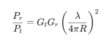
where Pr and Pt are the received and transmitted power, Gt and Gr are the transmitting and receiving antenna gains, λ is the wavelength, and R is the distance between the antennas.
2. Radiation Pattern Measurement Principle
The radiation pattern depicts the relative strength distribution of energy radiated or received by the antenna in different directions in space. It is a visual representation of the antenna's directivity.
Measurement Core: The measurement system rotates the positioner carrying the Antenna Under Test (AUT) while simultaneously recording the signal strength received by the receiving antenna at each angular point.
Key Parameters: Radiation pattern analysis yields several important parameters:
Half-Power Beamwidth (HPBW): The angular width where the main lobe's amplitude drops to half of its maximum value (-3dB).
Side-Lobe Level (SLL): The ratio of the maximum power of the side lobe to the maximum power of the main lobe.
Polarization: Measurement of the antenna's response to different polarization directions.
Practical Operation Procedure: The Eight-Step Chamber Measurement Protocol
A standard, precise antenna measurement requires strict adherence to the following steps to ensure data accuracy and repeatability.
Instrument Calibration and Setup: Strict S-parameter calibration of equipment such as the Vector Network Analyzer (VNA) is performed to ensure impedance matching at the measurement ports.
Determining Far-Field Conditions: Ensure the testing distance R satisfies the far-field condition R≥2D2 /λ. This is a prerequisite for obtaining accurate gain and radiation patterns.
Antenna Under Test (AUT) Installation: Mount the AUT onto the positioner using low-dielectric constant support materials, ensuring the antenna's phase center is precisely aligned with the positioner's rotation center.
Standard Gain Horn (SGH) Setup and Calibration: The SGH serves as the reference benchmark; it is precisely installed, and its known gain data is input into the measurement software.
Radiation Pattern Data Acquisition: Set the rotation step size. The positioner begins rotating along the azimuth and elevation axes, and the system automatically records the received signal power, collecting data for at least two mutually perpendicular planes.
Antenna Gain Calculation: The software automatically calculates the AUT's absolute gain using the received power data from the substitution method, combined with the Friis Transmission Formula and the SGH's known gain.
Data Post-Processing and Analysis: The raw data is smoothed and corrected (e.g., for cable loss). Key parameters such as HPBW, SLL, and FBR are automatically extracted.
Generation of a Professional Measurement Report: All measurement parameters, setup details, test conditions, equipment calibration status, etc., are integrated to form a complete and traceable professional report.
Challenges and Solutions: Ensuring Measurement Accuracy and Reliability
Even in an ideal anechoic chamber, ensuring the final antenna measurement data is accurate and reliable requires specialized technical handling and strict quality control.
1. Eliminating Cable and Connector Loss
Challenge: Feeder cables and connectors introduce signal attenuation (loss), which can affect the precision of the gain value.
Solution: Port calibration and de-embedding operations must be performed using the VNA. By accurately measuring the cable loss at the operating frequency and subtracting it from the final result, the gain data is ensured to reflect the intrinsic performance of the antenna.
2. Far-Field Error and Near-Field Correction
Challenge: For large antennas or low-frequency measurements, strictly satisfying the far-field condition may require an impractically large chamber space.
Solutions:
Compact Range Antenna Test System: Utilizes a parabolic reflector to shape the beam from a near-field source into a quasi-plane wave, simulating far-field conditions within a smaller anechoic chamber.
Near-Field to Far-Field (NF-FF) Transformation: If only near-field measurement is feasible due to chamber constraints, complex mathematical algorithms (such as planar, cylindrical, or spherical near-field scanning) are used to calculate and derive the equivalent far-field radiation pattern and gain.
3. Preventing Positioner and Support Structure Scattering
Challenge: Metallic components used to support and rotate the AUT can scatter electromagnetic waves, distorting the radiation pattern.
Solutions:
Use low-dielectric constant, low-loss foam or polystyrene materials as antenna support structures.
Utilize the Anechoic Chamber Background Subtraction technique: The background field (with only the stand and positioner) is measured first, and then subtracted from the antenna measurement to purify the data.
Conclusion and Call to Action
Accurate antenna performance measurement is the cornerstone for ensuring your wireless products succeed in the market. We are well-versed in overcoming various testing challenges, ensuring that the data you receive is credible, traceable, and compliant with international standards.
Do you require high-precision, error-free antenna test data to accelerate your product launch?
We possess top-tier anechoic chambers and a team of experienced professional engineers.
If necessary, please contact us as soon as possible!


