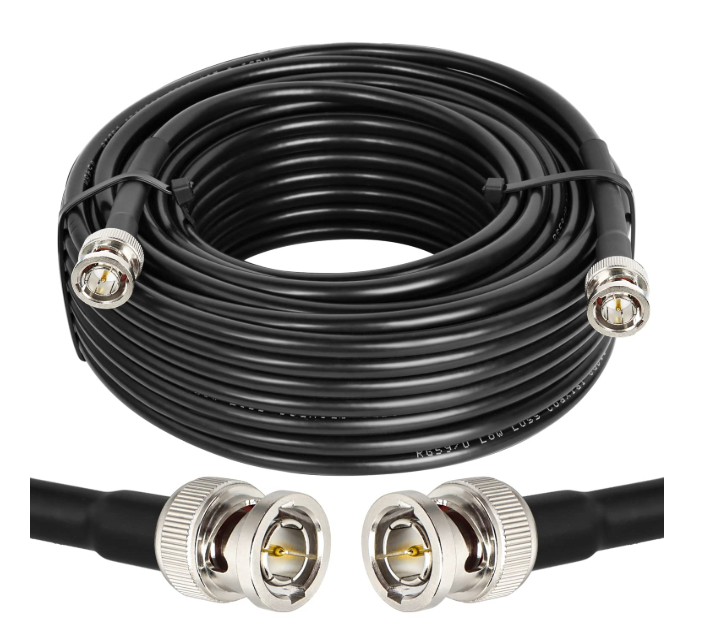
In the modern field of electronic communications, RF coaxial cables are key components widely used in scenarios such as wireless communications, radio and television, and radar navigation. They consist of an inner conductor, an insulating layer, an outer conductor, and an outer sheath. The inner conductor transmits signals and can be a single solid wire or a multi-strand twisted wire; the insulating layer is made of materials such as polyethylene to maintain electrical isolation and structural support; the outer conductor is mainly made of braided copper mesh or aluminum foil to shield electromagnetic interference; the outer sheath protects the cable from environmental erosion. Its core advantage lies in confining electromagnetic energy within the medium for transmission through a concentric structure, achieving signal transmission with low attenuation, high shielding performance, and a wide frequency band, making it particularly suitable for microwave frequency scenarios.
I. Core Characteristics
(1) Characteristic Impedance
This is a key indicator determining signal transmission efficiency, directly related to the size ratio of the inner and outer conductors, and significantly affected by the skin effect. The common 50-ohm impedance can balance power transmission and loss, adapt to most equipment, and is widely used in fields such as wireless communications; 75-ohm is mostly used in cable television networks (CATV), with a transmission bandwidth of up to 1GHz, and the bandwidth of commonly used models is 750MHz.
(2) VSWR and Return Loss
VSWR reflects the degree of signal reflection, and a smaller value indicates better cable consistency. The VSWR of typical microwave cable assemblies is between 1.1-1.5, corresponding to a return loss of 26.4-14dB, and the transmission efficiency reaches 96%-99.8% at this time. In practical applications, a VSWR of less than 1.5 can meet most needs.
(3) Attenuation Performance
Attenuation (insertion loss) is composed of dielectric, conductor, and radiation losses. The higher the frequency and the smaller the conductor size, the more obvious the attenuation, and increasing temperature will also aggravate the loss. When selecting, it is necessary to consider the transmission distance and frequency to ensure effective signal transmission.
(4) Power Capacity
It is divided into peak and average power capacity. The former depends on the voltage resistance capability, and the latter is related to the heat dissipation capacity, affected by factors such as the temperature resistance of the medium, ambient temperature, and altitude. It needs to be comprehensively considered in combination with the actual power and frequency.
(5) Other Characteristics
The propagation speed is inversely proportional to the dielectric constant of the medium. The smaller the dielectric constant, the closer it is to the speed of light, which helps in fault location; passive intermodulation distortion is caused by nonlinear factors and can be reduced by high-quality materials; phase stability during bending is crucial for systems such as phased arrays, and low-density dielectric cables perform better.
II. Selection Criteria
(1) Impedance Matching
It needs to be consistent with the impedance of system equipment. 50-ohm is selected for most scenarios, and 75-ohm is preferred in the radio and television field to avoid signal reflection and efficiency loss.
(2) VSWR and Return Loss
Priority is given to products with small VSWR and large return loss. Higher standards are required for high-precision scenarios, and attention should also be paid to the performance stability of the full frequency band.
(3) Attenuation and Power
For short-distance testing, cables can be selected according to the tolerance of the equipment, and low-loss models are required for long distances; for high-power scenarios, the power capacity must be strictly matched, and evaluated in combination with factors such as frequency and environment.
(4) Shielding and Durability
In environments with strong electromagnetic interference, cables with high shielding efficiency are required. Single-layer, double-layer, and triple-layer shielding are respectively suitable for different frequencies and scenarios; for scenarios with frequent bending, attention should be paid to bending life and phase stability, and for testing environments, the plug-in life of connectors should be considered.

III. Typical Applications
(1) Wireless Communications
It is used for connecting base stations and antennas, inside mobile terminals, and wireless access points. Cables with low loss, high shielding, and impedance matching are required, and flexible cables are suitable for the needs of miniaturized equipment.
(2) Radio and Television
75-ohm cables are the core of cable television networks, and amplifiers need to be used for long-distance transmission; transmitters use them to connect transmitters and antennas to ensure the breadth of signal coverage.
(3) Radar and Navigation
Radar systems rely on cables with high power capacity, low loss, and strong shielding to transmit pulse signals; in navigation equipment, stable transmission of weak satellite signals is required to ensure accurate positioning.
With its unique structure and performance, RF coaxial cables have become the "nerve channels" of modern communications. Understanding their characteristics and selection logic can better meet the needs of various scenarios.


