Yagi-Uda Antenna and Its Design Method
The Yagi-Uda Antenna is a directional antenna widely used in radio communication, renowned for its high gain, strong directivity, and relatively simple structure. Invented by Japanese scientists Hidetsugu Yagi and Shintaro Uda in the 1920s, it is mainly applied in fields such as television reception, radio communication, and radar systems. This article will elaborate on the basic principles, structural composition, and design methods of the Yagi-Uda antenna.
I. Basic Principles of the Yagi-Uda Antenna
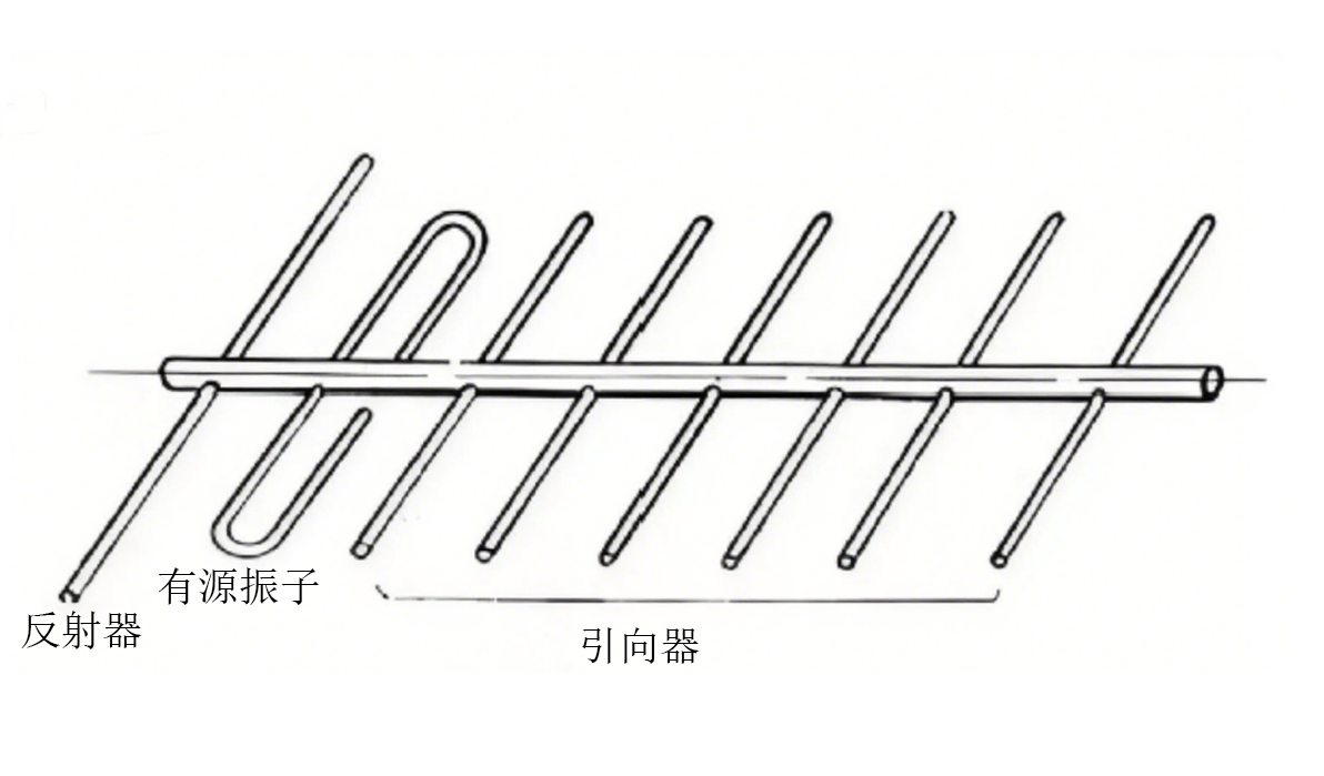
The Yagi-Uda antenna is an end-fire antenna array, and its working principle is based on the radiation and reception of electromagnetic waves. It achieves directional radiation through multiple parallel - arranged oscillators (usually metal rods). These oscillators include one active element (typically a half - wave dipole) and multiple passive elements (including reflectors and directors). The active element is directly connected to the feeder and is responsible for the transmission or reception of electromagnetic waves; the passive elements interact with the active element through electromagnetic coupling to adjust the radiation direction of the electromagnetic waves.
The directivity of the Yagi-Uda antenna mainly depends on the arrangement and length of the passive elements. The reflector is located behind the active element, usually slightly longer than the active element, and is used to reflect electromagnetic waves to enhance the forward radiation of the antenna. The director is located in front of the active element, usually slightly shorter than the active element, and is used to guide electromagnetic waves to further enhance the forward radiation. By reasonably designing the length and spacing of the reflector and director, high - gain and narrow - b
eam radiation characteristics can be achieved.
II. Structural Composition of the Yagi-Uda Antenna
The basic structure of the Yagi-Uda antenna includes the following parts:
Active Element: The active element is the core part of the Yagi-Uda antenna, usually a half - wave dipole, responsible for the transmission or reception of electromagnetic waves. It is directly connected to the feeder and is usually located at the center of the antenna.
Reflector: The reflector is located behind the active element, usually 5% - 10% longer than the active element. Its function is to reflect electromagnetic waves, reduce backward radiation, and enhance forward radiation. There is usually only one reflector, but multiple reflectors can also be designed to further improve directivity.
Director: The director is located in front of the active element, usually 5% - 10% shorter than the active element. Its role is to guide electromagnetic waves and further enhance forward radiation. The number of directors can be adjusted according to the gain and directivity requirements of the antenna, usually ranging from 1 to 10.
Boom: The boom is used to fix the active element, reflector, and director, and is usually a long rod made of metal or non - metallic materials. The design of the boom needs to consider the mechanical strength and weight distribution of the antenna
Feed Line: The feed line is used to connect the active element to the transmitter or receiver, usually a coaxial cable or twisted pair. The impedance of the feed line needs to match the impedance of the active element to reduce signal reflection and loss.
III. Design Method of the Yagi-Uda Antenna
When designing a Yagi-Uda antenna, several parameters need to be considered, including operating frequency, gain, directivity, and impedance matching. The following are the basic steps for designing a Yagi-Uda antenna:
Determine the operating frequency: First, it is necessary to determine the operating frequency range of the antenna. The size of the Yagi-Uda antenna is closely related to the operating frequency; the higher the frequency, the smaller the size of the antenna. Generally, the operating frequency range of the Yagi-Uda antenna is from several tens of MHz to several GHz.
Select the type of active element: The active element is usually a half - wave dipole, and its length is approximately half of the operating wavelength. The length of the half - wave dipole can be calculated by the following formula:
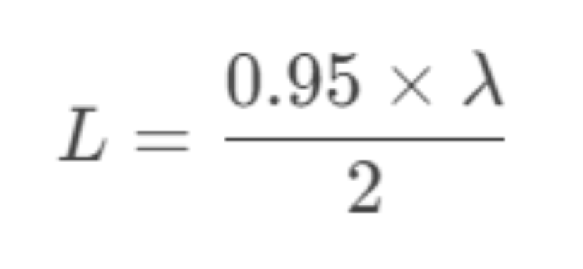
(where L is the length of the oscillator and λ is the operating wavelength. 0.95 is the shortening coefficient.)
Design the reflector and director: The length of the reflector is usually 5% - 10% longer than that of the active element, and the length of the director is usually 5% - 10% shorter than that of the active element. The distance between the reflector and the active element is usually 0.15 - 0.25 wavelengths, and the distance between the director and the active element is usually 0.1 - 0.15 wavelengths. The specific length and spacing can be optimized through simulation software or empirical formulas.
Determine the number of directors: The number of directors directly affects the gain and directivity of the antenna. The more directors there are, the higher the gain of the antenna and the narrower the beam width. However, an excessive number of directors will increase the complexity and size of the antenna. Usually, the number of directors ranges from 1 to 10, and the specific number needs to be weighed according to the application requirements
Impedance matching: The impedance of the active element is usually 50Ω or 75Ω, which needs to match the impedance of the feeder. Impedance matching can be achieved by adjusting the length and diameter of the active element or using an impedance matching network.
Simulation and optimization: After the design is completed, electromagnetic simulation software (such as HFSS, CST, etc.) can be used to simulate the antenna to verify its performance. The gain, directivity, and impedance matching of the antenna can be optimized by adjusting parameters such as the length and spacing of the oscillators.
Fabrication and testing: A prototype antenna is fabricated according to the design results, and tested using equipment such as a network analyzer and a spectrum analyzer to verify the actual performance of the antenna. Further optimization is carried out according to the test results.
IV. Advantages and Disadvantages of the Yagi-Uda Antenna
Advantages
· High gain: The Yagi-Uda antenna has a relatively high gain, usually 10 - 20dBi, which is suitable for long - distance communication.
· Strong directivity: The Yagi-Uda antenna has a narrow beam width and strong directivity, which can effectively reduce interference.
· Simple structure: The structure of the Yagi-Uda antenna is relatively simple, making it easy to fabricate and maintain.
· Low cost: The material cost of the Yagi-Uda antenna is low, making it suitable for large - scale applications.
Disadvantages:
· Narrow bandwidth: The bandwidth of the Yagi-Uda antenna is relatively narrow, usually 5% - 10% of the operating frequency, so it is not suitable for broadband applications.
· Large size: The size of the Yagi-Uda antenna is inversely proportional to the operating frequency. Antennas in the low - frequency band have a large size, which is not suitable for applications with limited space.
Fixed direction: The directivity of the Yagi-Uda antenna is fixed, and it needs to be adjusted manually, so it is not suitable for scenarios where the direction needs to be changed frequently.
V. Applications of the Yagi-Uda Antenna
The Yagi-Uda antenna is widely used in the following fields:
· Television reception: The Yagi-Uda antenna is a common form of television receiving antenna, used to receive terrestrial television signals.
· Radio communication: The Yagi-Uda antenna is used in communication systems such as amateur radio, broadcasting stations, and wireless local area networks.
· Radar systems: The Yagi-Uda antenna is used for target detection and tracking in radar systems.
Satellite communication: The Yagi-Uda antenna is used to receive satellite television signals and satellite communication signals.
VI. Conclusion
The Yagi-Uda antenna is a classic directional antenna with the characteristics of high gain, strong directivity, and simple structure. Excellent radiation performance can be achieved by reasonably designing the length and spacing of the active element, reflector, and director. Although the Yagi-Uda antenna has disadvantages such as narrow bandwidth and large size, its wide application in fields such as television reception, radio communication, and radar systems proves its importance and practicality. With the development of electromagnetic simulation technology, the design and optimization of the Yagi-Uda antenna have become more efficient and accurate, and it will still play an important role in the field of wireless communication in the future.


